Assignment:
A_ design and build a wired and/or wireless network connecting at least two processors.
A_ design the network
I will make the hellobus.45 asynchronous bus. I researched documentation of students from previous year who had done this same exercise for this assignment and found the one from Edgaar R. Arenales, a fellow student from my Fablab who made a straightforward documentation. I will use it to guide me through.
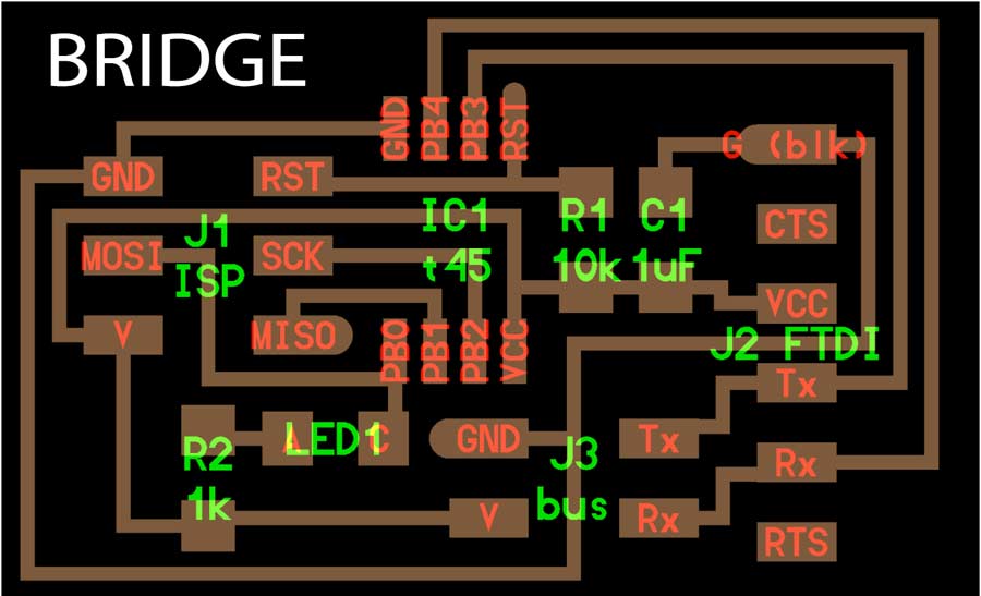
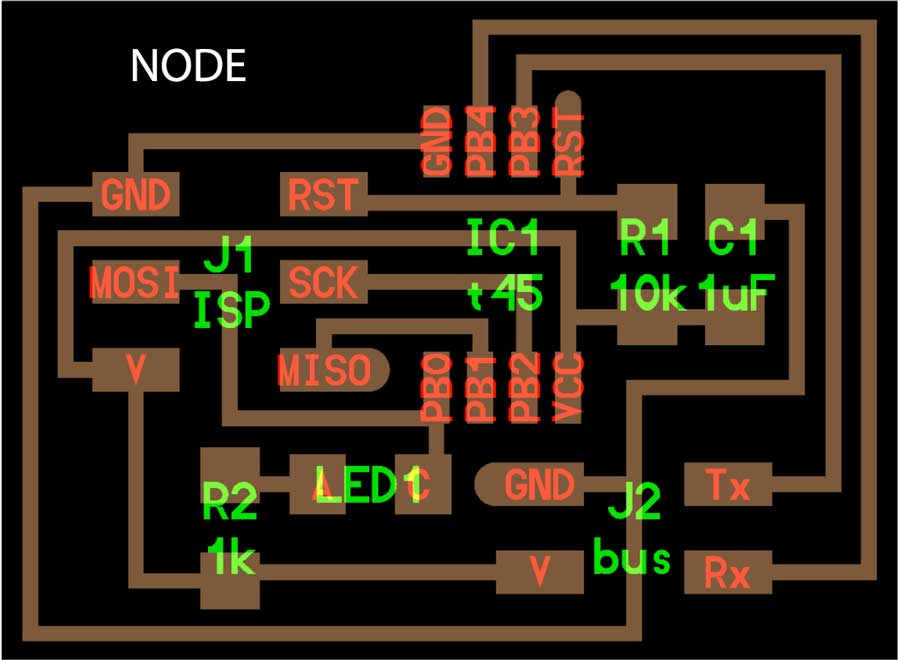
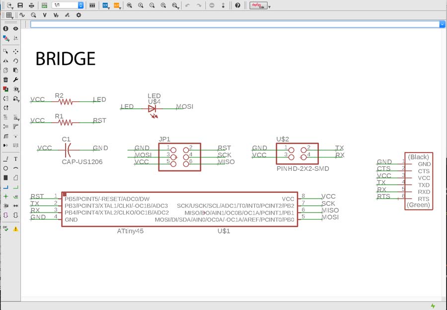
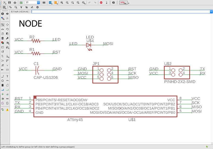
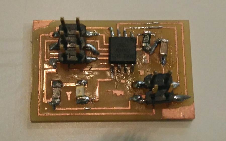
I started by producing the boards for the Bridge and the 2 nodes using Neil's design. I designed the schematic and the boards with Eagle.

The milling machine were collapsed on thursday in my lab so I could only manage to mill the bridge and had to wait for the day after so I decided to pair with my colleage < a href="http://archive.fabacademy.org/archives/2017/fablabbcn/students/51/">Trinidad Gomez who was in the same situation but had managed to mill her 2 nodes and not her bridge. At least we did not get stock and later once the lab calms down we could mill our own boards.
So together we went on stuffing our boards and tested each of them making shure there are no short circuit.
1-Programming the boards
The programming is a step by step process in which both bridge and nodes is programmed seperately. I first downloaded the .C and Make files for both bridge and node and saved it on my desktop.
Programming the bridge
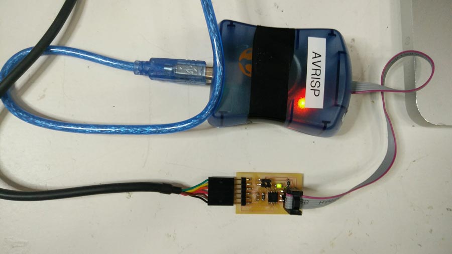
A- Connect the FTDI cable ( to power to the board) and connect the programmer (in my case avrisp2) to the 6 pin header.
B- open the .c file and locate the code line: #define mode_id '0' ( the 0 is the tag identifying the board - it could be whatever but I decided to leave 0 as the bridge tag).Save the file in a seperate folder.

C- In terminal go to the directory where the .make file is stored and type:
make -f hello.bus.45.make program-avrisp2
The led on the Bridge board should lights up, the Avrisp light turn orange (while programming) and turn green again when programming is completed. Terminal should compile (no error message) and led remained off after completion.
1-Programming the nodes
Proograming the nodes consist of repeating exactly the same process but powering the node unsing the GND and VCC pins of the 4 pin headers. Obviously the tag in the .C file needs to be edited also.
A- program the 1º node by conecting the programmer (in my case avrisp2) to the 6 pin header and providing power to the node (by connecting the VCC and GND of the 4 pin headers respectively to the VCC and GND of the node.
NOTE: Power can be provided to the NODE also simply by connecting VCC and GND from an Arduino or even through the ftdi cable.
B- open the .c file and locate the code line: #define mode_id '0' and change the 0 for a 1 ( or whatever you feel like but needs to be different from the bridge).

C-go to terminal, to the directory where the .make file is stored and type:
make -f hello.bus.45.make program-avrisp2
The led on the node board should light up, the Avrisp light will turn orange (while programming) and turn back to green when programming is completed. Terminal should compile (no error message) and led of the node turn off after completion.
To program the 2º node I repeated exactly the same operation after editing THE I.D OF THE NODE IN THE .C CODE. Otherwise 2 nodes will have the same ID and will act as if they were the same. Also make shure to save the file in a different location than where the first node -c file is saved.
Trouble shooting
I managed to program the bridge but struggled to program the 1st node. Kept failing to load the program.
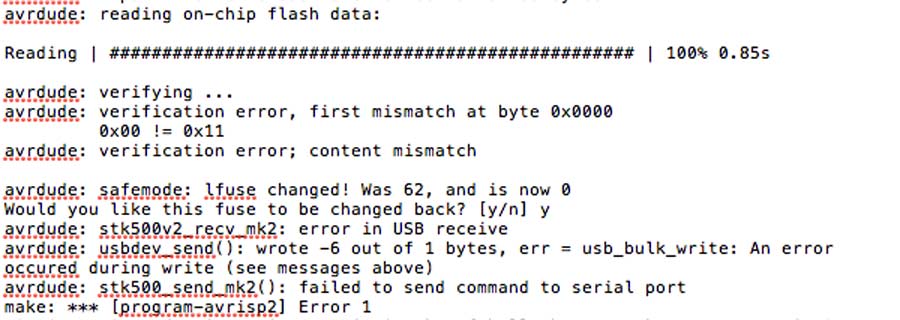
I tried a few times but repeatedly got error so I went back to the board and double-check the connections - no short circuits. I reviewed the board design and finally realized there had been confusion in stuffing the nodes and the resistors and capacitators had been soldered perpendicular to their proper position.
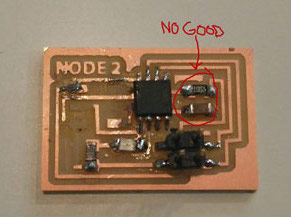
I unsorldered those 2 components and stuffed them as they should and completed the programming.
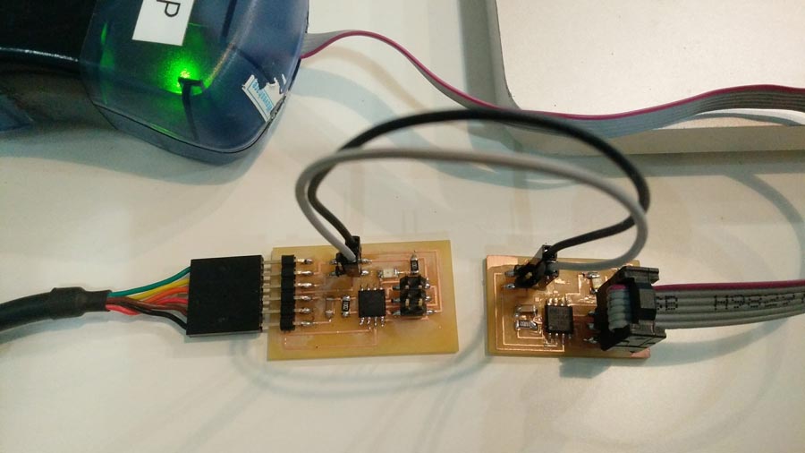
To verify the boards are programmed and work properly:
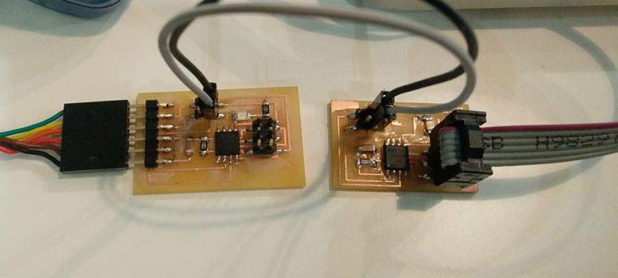
I connected the bridge to the FTDI cable and the node in series using the 4 pin header.
Make shure the right pins are connected properly on the bridge and each nodes. (GND, VCC, TX and RX pins)
Once the boards are connected:
-open ARDUINO IDE (no sketch needed)
-open the SERIAL MONITOR window.
-write 2 (for the 2º node) in the serial window and press SEND.
-Arduino compiles the code and shows the program in the serial window, and simultaneously the lights on the boards will blink.
The blinking sequence goes like that:
bridge and node flash at the same time and the node corresponding to the number entered in the serial window blinks once more. If I would have put 1 in the serial monitor window it is the 1st node that would have blink a second time.
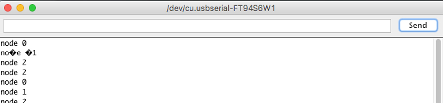
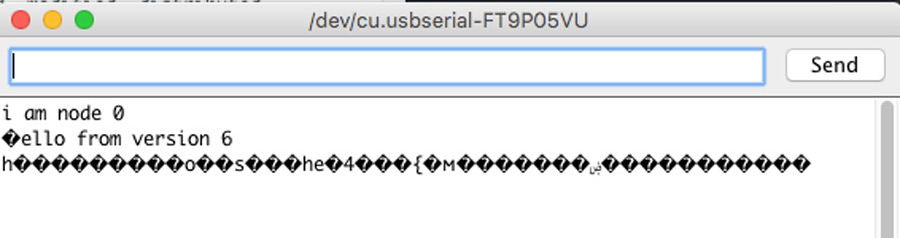
Note: I looked into the meaning of those "question mark" characters that appeared in the serial monitor window and I figured it must be due to a mismatching between transmitter and receiver encoding. It is strange as there were no strange characters in the commands I sent. Apparently this happens only when not standard ASCII characters are sent.
Milling and soldering is usual business by now. I lost lots of time troubleshooting the nodes and that took time that I had planned to invest into the programming part. Anyhow there is something that I found strange and I looked into it. During the .c and python workshop we had a few weeks ago, our instructors emphasized the fact that in serial communication the TX and RX pins are always crossed between 2 connected nodes. But the boards (bridge and nodes) are serial bus and connects TX with RX in a linear way (not crossed). I researched and figured that this crossing do not necessarly have to happen through hardware. It can be programmed in software. Analysing Neil's .C code I identified the lines that makes this function.
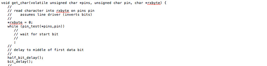

For the programming of the assignment I worked with Neil's C code. I asked a friend who understands low level C language to guide me in adapting it for the led to perform differently. I targeted primarly the main and added a print_version function Hello from version "x" + the master to make a long blink and the slave respond with his name and makes 2 small blinks.
Lists of edits we did in the code.
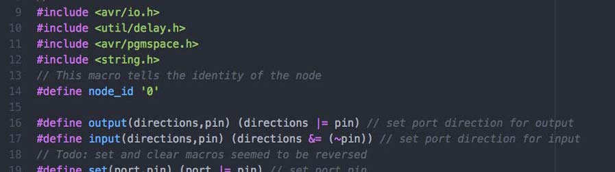
-move the node_id up to the first in the define list.
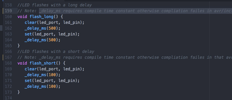
-removed the led delay macro and call the flash function directly.
-make flash function to long blink + add a flash function for shorter blink
Note: We tried to add a variable as a flash argument but could not compile. _delay_ms requires compile time constant otherwise compliation failes in avr/include/util/delay.h. We opted to just create the function and repeat it which is what we wanted to by-pass.
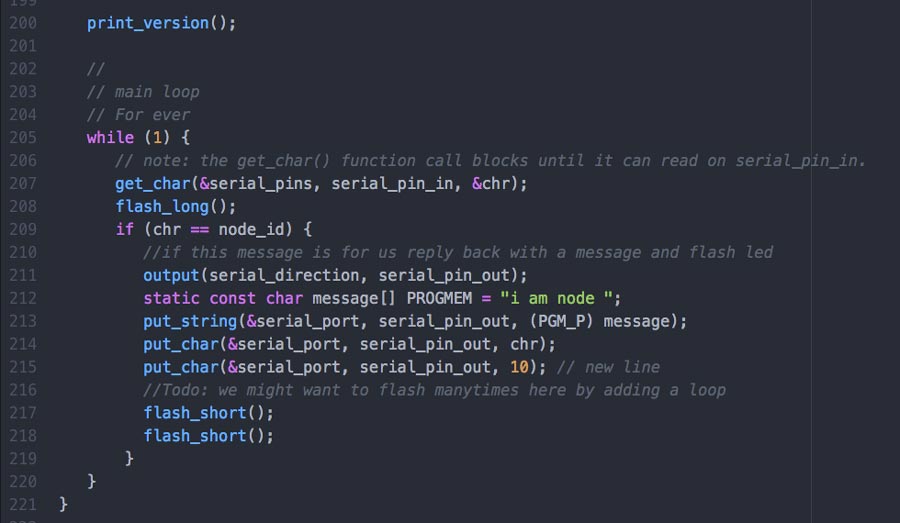
-Write a message when we start.
-Respond with a message when signal is for you
-adjust blink frequency and timingp
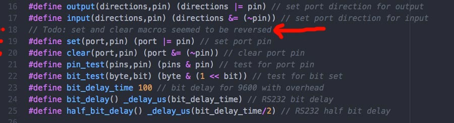
The way we worked with Henrik was him to help developping logic, syntax and learn to comment code properly.That includes "Todo's" comments for future iteration inserting "..
Note: When testing the code and how it worked we found out that the clear and set commands seemed to be inversed. The way Neil's code is when the program stat the blink should be off but the code says: set. We tested by putting clear and the led then is on.
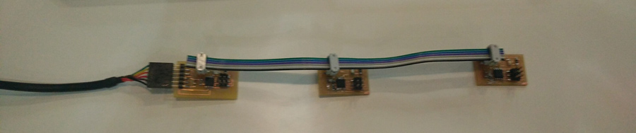
I managed to program the master and 3 more slave and they reacted as planned:
When sending 0 all the nodes make a long flash and the master makes 2 short flash.
When sending 1 all the nodes make a long flash and the 1st slave made 2 short flash.
etc. etc.
For reasons I have not yet discovered yet I could only print the "I am node " " message with the master and only when no other nodes are connected. None of the slave would print their response. Neither would they print the welcome message when they are connected for the first time. It may be the connections. In many cases the " hello from version 6 " did not either print, and some other times it would print with funny characters and sometimes it would print normal. The funny characters are related to the connection indicating the data of the response is not a recognizable character.
I also used this session to integrate git in my workflow. I created a remote repository on gihub and pushed the different versions throughout the Hello.bus.edit.c session. It was the first time that I experimented with version control outside the Fablab gitlab and it gave me good practice to use diff, commit am "" commands and created a script to add ssh key for repository access.
Conclusion
Lessons for this week: Simple mistakes can lead to heavy troubleshooting. Using my fellow student board instead of milling my own made me waist a lot of time and energy. It made me learn to collaborate also and this I enjoyed but I wished I would have had more time to invest into understanding coding which remains a weak point in my skill development.
I feel I am breaking the ice with coding. By getting familiar with low level C code I am starting to understand more the logic of programming. Still all very new but making progress. And that feels good.