Assignment:
A_Create and cut a vynil cut project
B_Make a goup exercise
C_ Design, make and document a parametric press-fit construction kit.NOT COMPLETED
B_Make a goup exercise
C_ Design, make and document a parametric press-fit construction kit.NOT COMPLETED
A_Use Vynil cutting tool
I started by studying the instruction manual of the vynil cutter we have in our lab (Roland-1 Servo_GX-24)) and reviewed the Fablab Wiki vynil cutting page and went on cutting my exercise.
While vynil cutting seems as a fairly simple operation there are specific steps to follow:
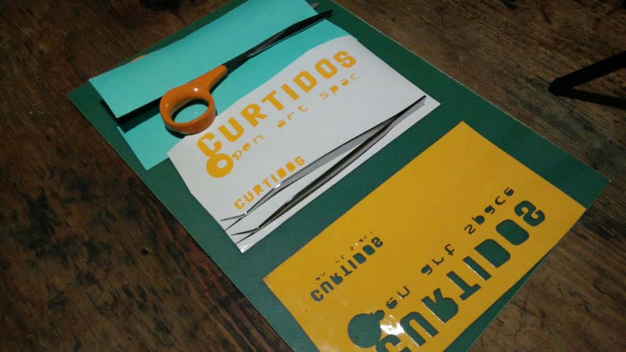
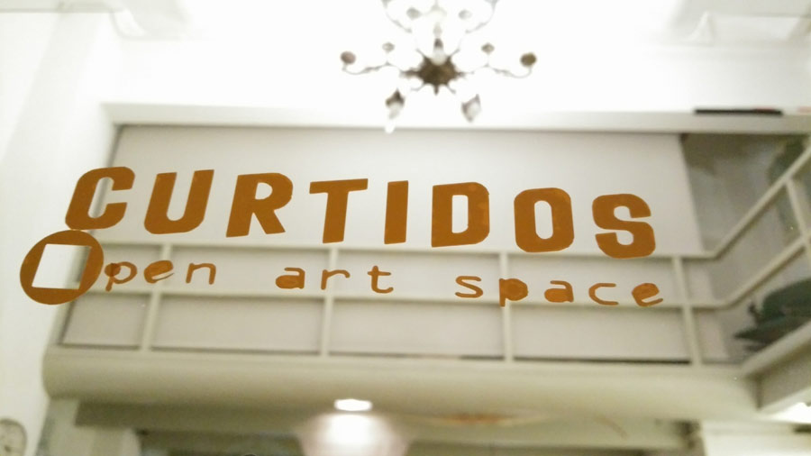
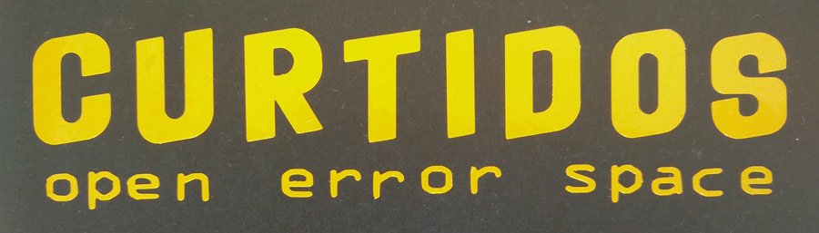
I designed a sticker logo for the front door of the art space and studio. I used a pictures of the real sign and scaled the letters using Illustrator. As the original is designed vertically I extracted each letter and placed them on a horizontal axis and added "art space". I did variations in terms of layouts, and finally decided to keep the version on 2 lines. Of that one I also did one version with a thin line (0,057) around the letters and another with thick (1.5 pt) line to get only the contour of the line, leaving the interior empty.
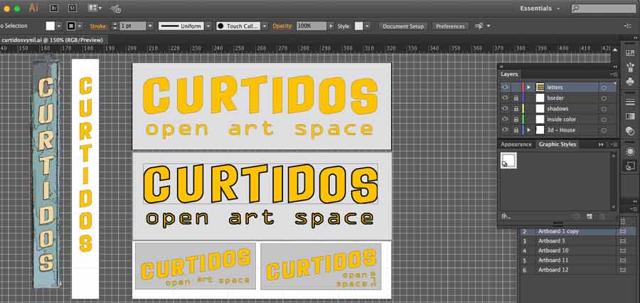
Then I imported the file to Inkscape to preparte it for the Vynil cutter. To get more points of references (vectors) into the files our instructor recomended to open the file in inkscape and stretch the image x 3. This adds more points and gives more defenition to the drawing and helps a better cuttig job.
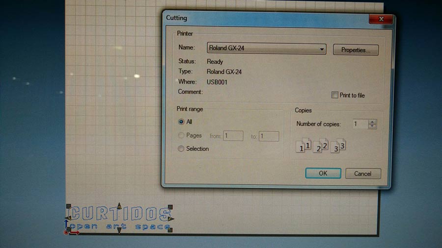
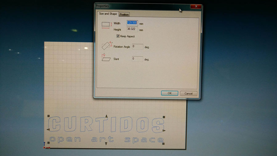
Afterwards I imported the image into Roland sftware Cut Studio, and prepared the job which consist of setting the media size, the cut settings, the origin point and save file.
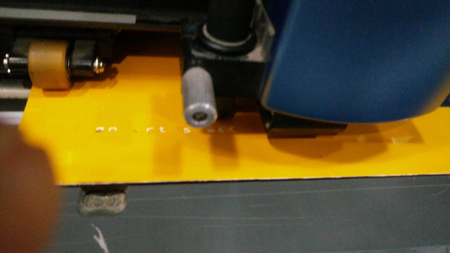
I am using yellow vynil and take advantage a left over. The vynil needs to be inserted into the machine from the back, releasing the lever on the back of the machine and sliding the material in until it reaches the yellow tag on the front part, aligning it with the guidelines, and positioning it properly along with the grit mark and the pinch roller
Once the material is placed the machine can be turned on: the cuting carriage moves to the left pinch rolller position and the machine measures material size and sets it-self up accordingly.
The blade needs to be adjusted according to the material used. It consists of adjusting how far the blade tip comes out of the holder. It is preferable to have the blade too much inside instead of the opposite and adjust it out through testing until the vynil peels perfectly from the base layer without having it be cut through.
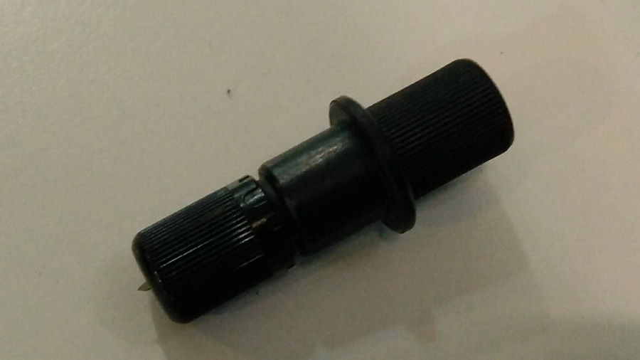
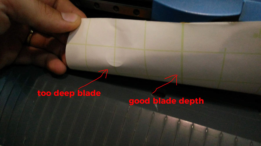
It is recommended to run a test to make shure the balde is set properly. Set the origin (make shure to set the origin close from the cutting test area).
The machine was setup properly and I am ready to send the file to cut.
I first sent the design with the tick line but it did not worked well. The body (line size) was too small for the machine to cut it as a contour - in other words the size of the line was too small to have the machine cut on each sides- so it clugged on the blade which made the material move and the result was useless.
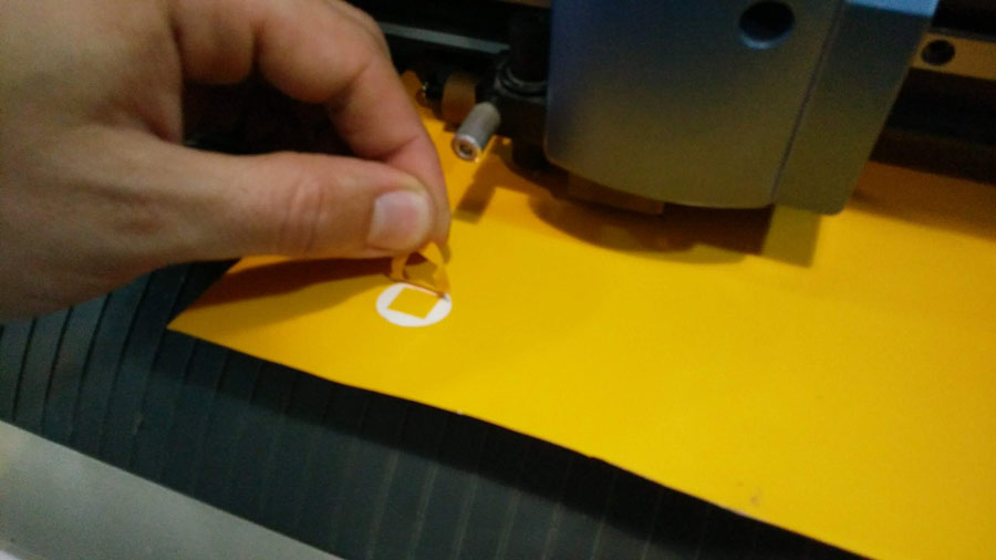
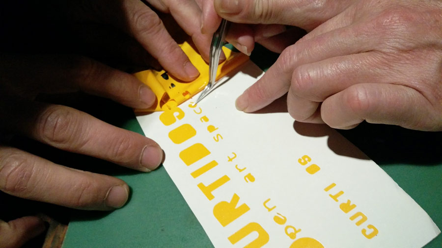
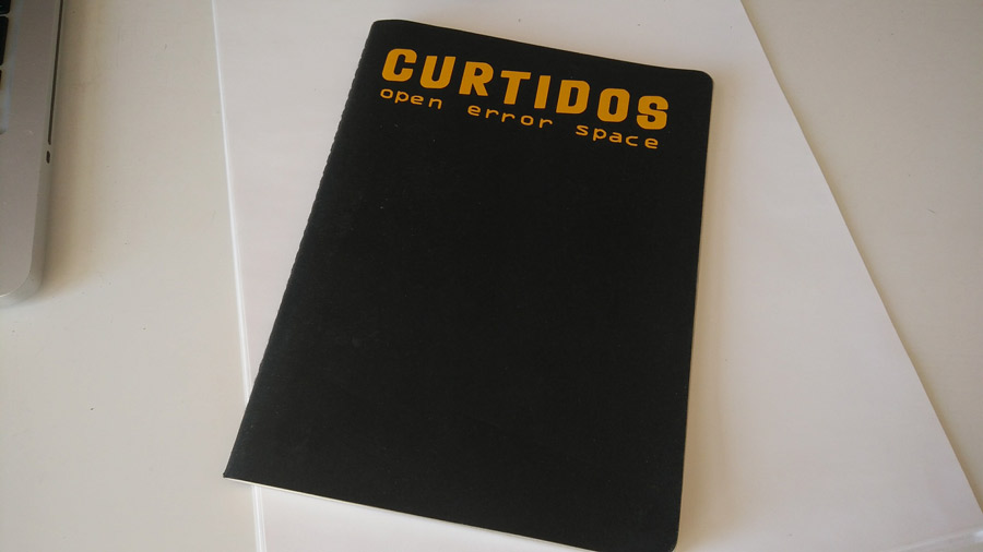
I repeated the inskape operation with the thin line version. The result was much better but the depth of the blade was a little bit off and some areas (the inside of the letter mostly) were difficult to peel. Seen this I decided to take advantage of the mistake and leave the interior part of some of the letter as it adjusts perfectly to the spirit of the project. Open, playful, free and unbounded creativity.
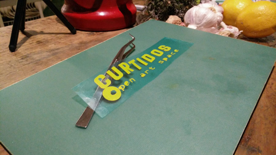
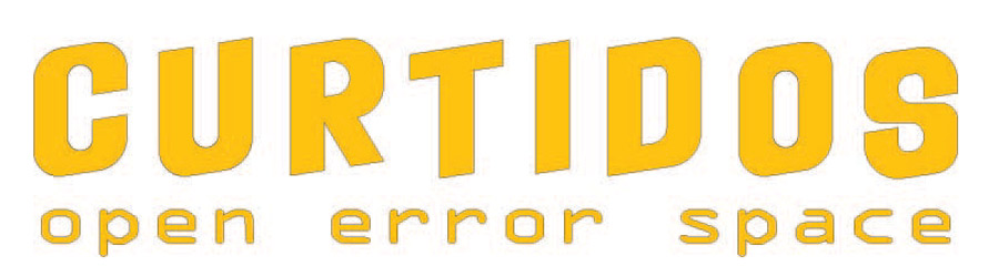
I reflected on the error factor in a creative process. I consider it as a fundamental dimension which largely contribute to new findings, and often surprising results. I am curious to explore this idea - error, errorism, errorist - make representation of it, and even embed it into the very object and/or the technology and interactive experience.
Already feeling uncomfortable from the start with the "art space thing, I changed the logo to "open error space" and repeated the exercice with this new logo.
B_Laser cutting assignment
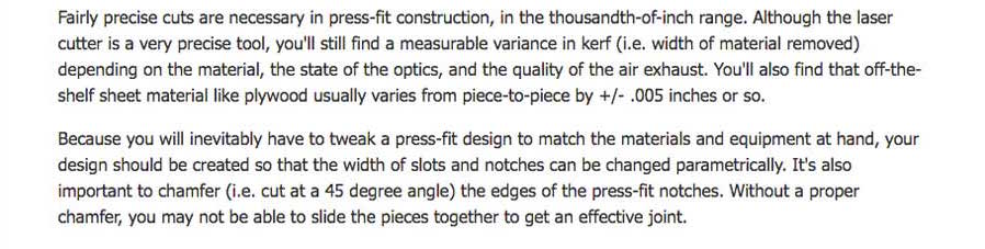
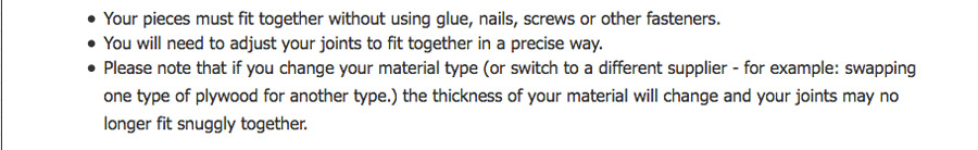
The objectives of the laser cutter part of the assignment are very well explained in this Press-Fit construction Tips tutorial.
The group exercise consists in testing different combination of laser cutter parameters (speed, power and resolution) in cut and engrave operation using both vector and raster mode. I have experience from previous years and my group is composed of 2 other continuing/non fulltime students who are not available this week to work in group. So I made an extra exercise by my-self to proove my skills with laser cutting technique and machines.
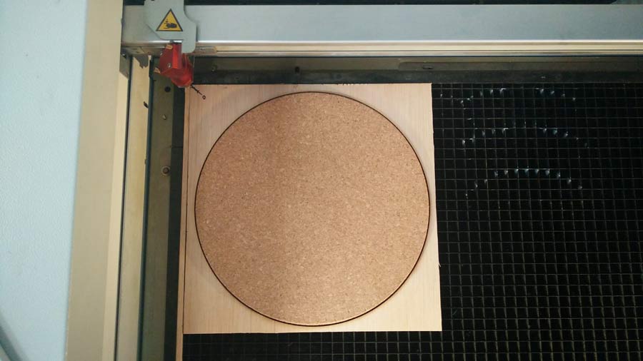
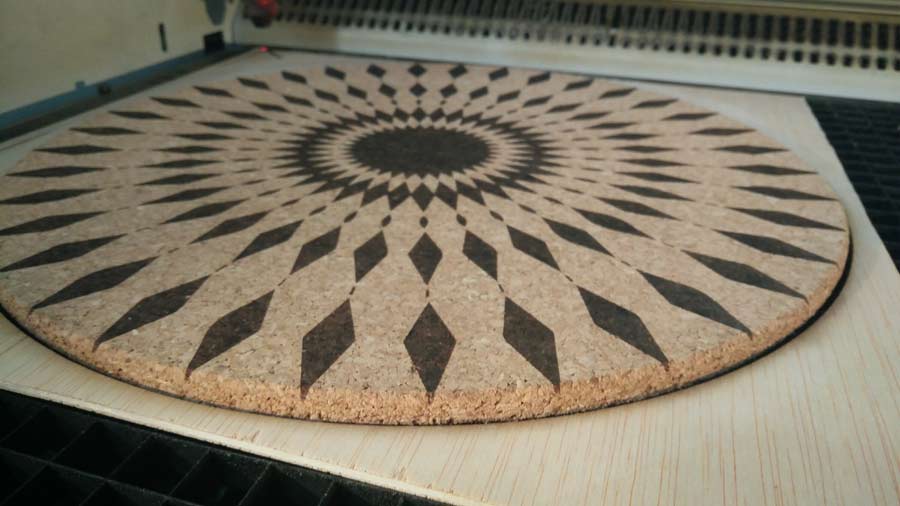
My idea is to engrave a graphic pattern on a 30cm diameter circle of 5 mm. thick cork. As in other digital fabrication processes laser cutting implies 4 important steps:
-prepare the file
-prepare/set the machine (laser cutter)
-perform the cutting
-assemble
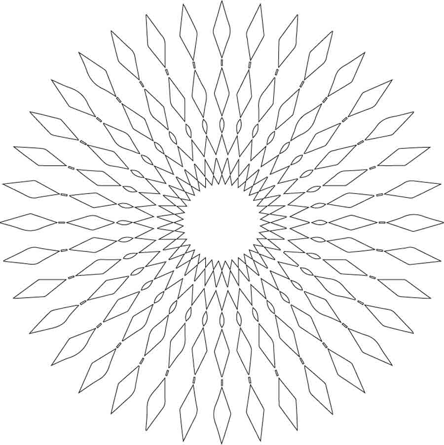
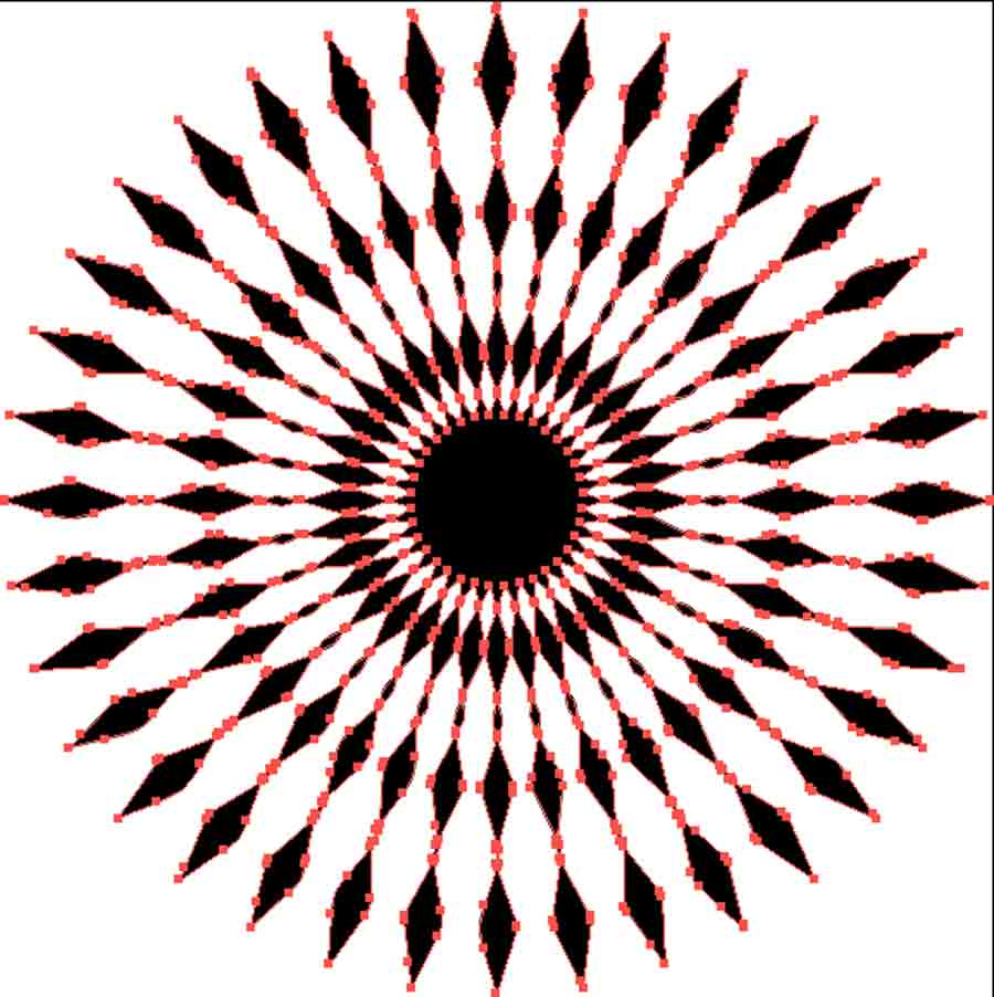
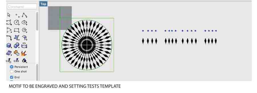
I started with a PNG file, filled the interior of the rhombus with Photoshop, converted it to vector graphic with Illiustrator, and then opened, edited, and prined it using Rhino.
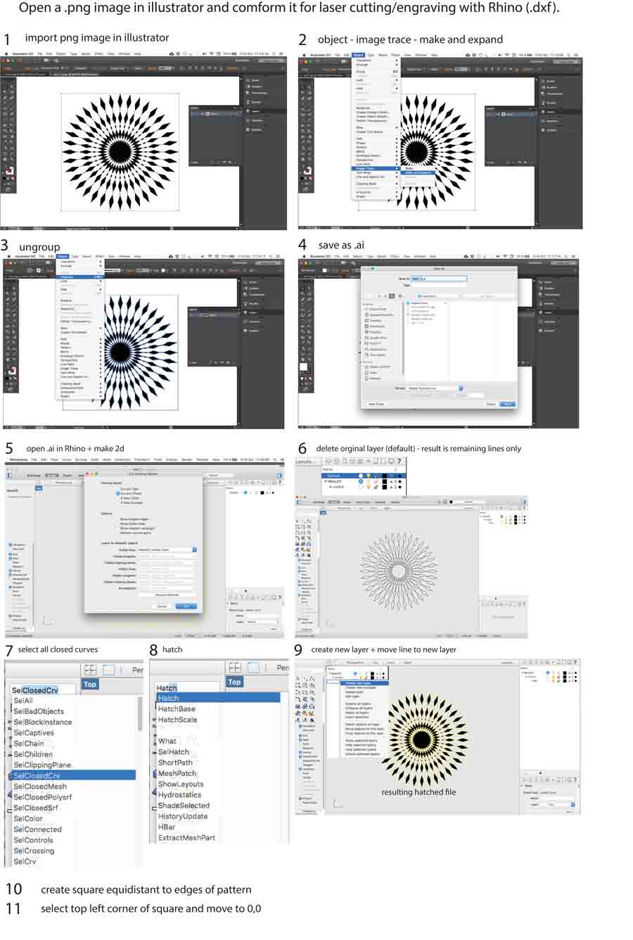
- import PNG in Illustrator.
- converted the file to Vector graphic using image trace/make.
- ungrouped the objects.
- save file as .ai format.
- open .ai file in Rhino.
- make2D command to make shure all objects are on the same plane.
- delete the original layer.
- select all the closed curves (selcloseCrv).
- hatched (hatch) the interior of all curves.
- finally create a new layer and moved the lines (closed curves) to that layer making it easier to decide to either print the curve and the hatch together or not.
I also placed the diferent parts of the pattern on respectiv layers so I can easily make variation with each unit I print.
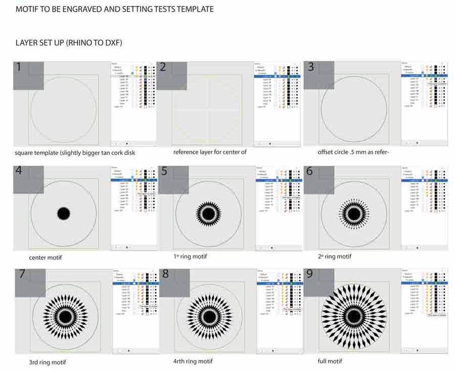
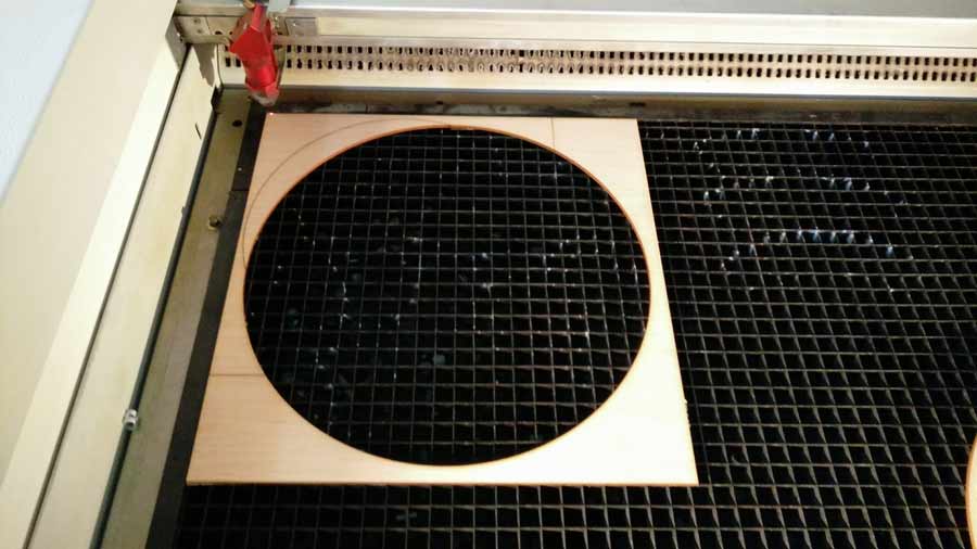
Next I created a template to be cut in 3mm balsa wood and which contains a circle the same size as the pattern i want to engrave and a square equidistant to the edge of this circle. This way I can fix the template to the laser cutter table and place the piece of cork I want to engrave on in the circle cutout. This way I can easily engrave various units with the same setup.
Machine and print jobs and parameters
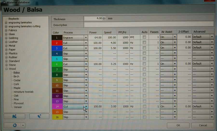
I am using the Trotec 400 laser cutter machine. Reading the Trotec 400 instruction manual is very important before turning it on. Even after we have received the short introduction by the instructor. The ideal set up is made of a combination between power, speed and Resolution /PPI. Those are the main parameters but there are others for experienced users and/or for very speficic applications.
- Power: the output power of the laser in a range of 0 to 100%.
- Speed (velocity): the movement of the laser head. Fast speeds lead to short exposure times, slow speeds lead to long exposure times.
- PPI or frequency: (pulses per inch) determines how many laser pulses per inch are used for the engraving. To achieve a good result this should be the same or a multiple of the DPI selected in the print setting of the vector file. Auto mode will automatically set a PPI according to the DPI setting.
- The Pass parameters is helpful to avoid stessing the material while engraving. It allows to engraving by passing few times over the material instead of doing it at once. Few pass with less power (or more speed) instead of one pass at fiull power and speed.
- Air assist: sends compressed air to the lens as it cuts helping keeping it clean and free of dust. In rare cases it is recommended to turn it off. Usually it is kept on.
- Z off set: to laser engrave or cut with the lens off focus. To create effect and in rare occasion.
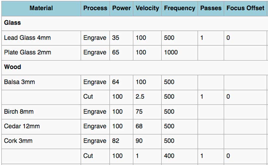
The best way to find the right parameters combination is to run tests with the exact machine and material that will be used. Not to start from scratch it is easy to find references on the web that gives orientation to start experiemtning. I found agood reference in the Fablab Berlin Wiki.
In our lab the Trotec400 drivers are linked to the print command of Rhino. By sending the file to print in Rhino the application "Job Control" opens automatically with the Print setup window. There are various parameters needed to be set from that window:
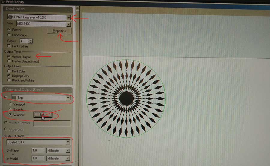
- The top needs to be set to the driver of the machine to be used: Trotec Engraver v10.3.0
- The property tab opens a new window that allows to tweaks the print size and material settings. The size can either be set to default (600 x 1000mm which corresponds to the surface of the laser cutter bed) or set manually to the size of the piece of material used.
- (The material settings they can also be set later in the process and directly from the setting tab of the Job Control main menu. I prefer that so I continued on with the Print setup.)
-select Vector (in case the input file is vector)
-In the VIEW AND OUTPUT SCALE select the TOP LEFT corner as the origin point of the job (where the laser is going to start cutting).
-Make shure the scale tab is set to "scale to fit" and below the unit on paper is the same as the unit in model. Otherwise there will be scaling happening altering the size of the print.
-Select "window" and click on the tab "SET". That send back to the Rhino window and allows to set a coincidence between the origin of the rhino drawing and the origin of the Print setup interface. In rhino Click the upper corner of the window and type in the command line: move 0,0 and Enter. A meesage pops-up asking to scale the image to the print window. CLICK NO. Press enter.
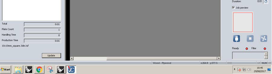
Click Print. The print window in the Job control opens. On the upper right side in a small window the queued file shows up. Click and drag the file to the big window (the print area), drag and drop it on the black cross on the upper corner in that window. If it does not snap it can be moved to the top left corner. It is important so the file is really located on the origin point.
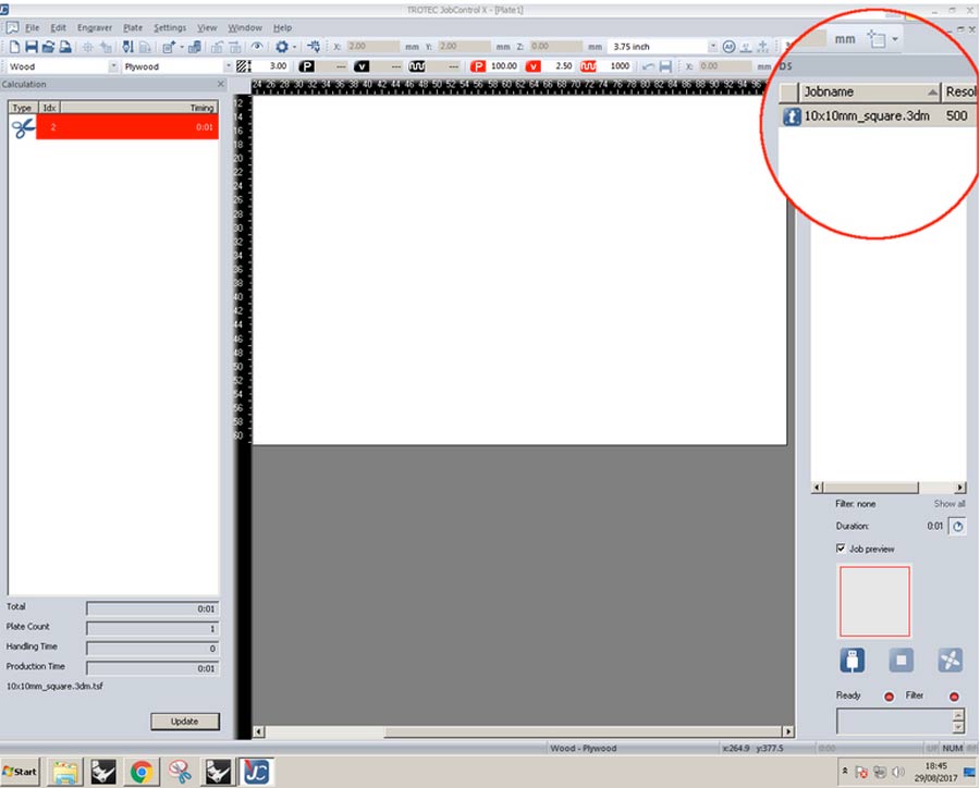
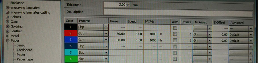
Once the file placed on the bed I opened the setting tab from the top menu and set the material settings to the sugested parameters of the Fablab Berlin wiki.
A the bottom left of the Job control window there is an usb connector icon showing when the Job control is not conected to the Laser cutter.
Before pressing this botton the machine needs to be turned on and set for the job.
Turning on and setting the Laser cutter and the material.
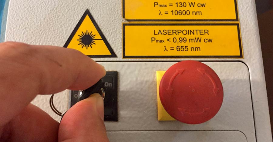
The main power of the Trotec turns on by switching a small key located next to emergency botton next to the control panel.
When switching the power on the filter unit turns on and the table travels to its lowest position. I placed the material on the bed (top-left corner of the material to the top left corner of the laser bed) and moved it up by pressing the Z up key on the control panel and up until there are about 8 cm betwen the tip of the lens and the surface of the material.
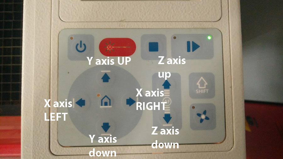
The laser needs to be focused exactly on the surface of the material. To do that we hang the "referencer" on a notch on the laser head and bring the table up manually little by little until the referencer tips off.
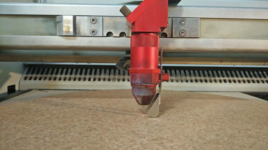
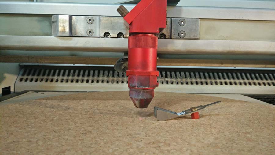
The Z axis is now set to focus and the laser head moves to its start position - until it lines up with the top left edge of the material.(the origin on both the rhino and job control.
Now the Job control interface can be connected to the Trotec and the job sent. Make shure the lid of the Trotec is properly closed and press PRINT.
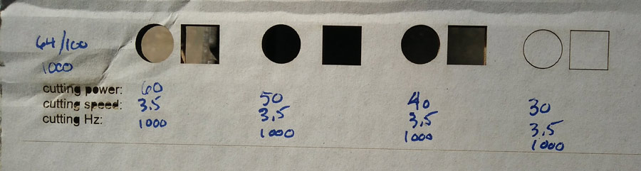
With the template ready I made a series of tests to find the right paremeters for cork engraving and reduced the options to 2 setups.
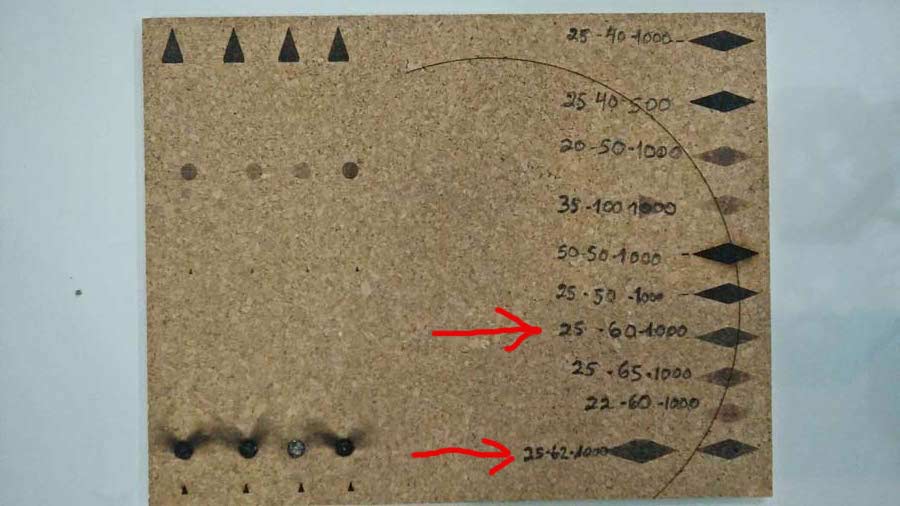
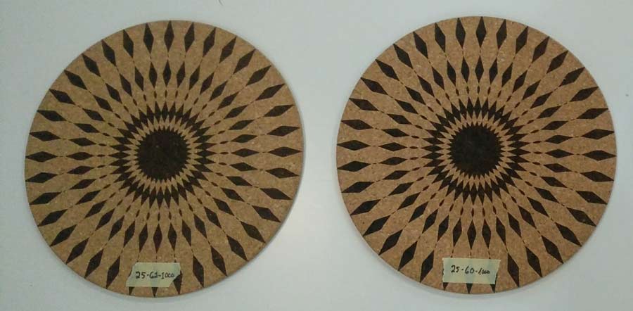
Then I engraved the whole pattern with both parameter set up and concluded p25/s60/ppi1000 gives the best result. Engraving is sharper and even thoughout the whole surface.
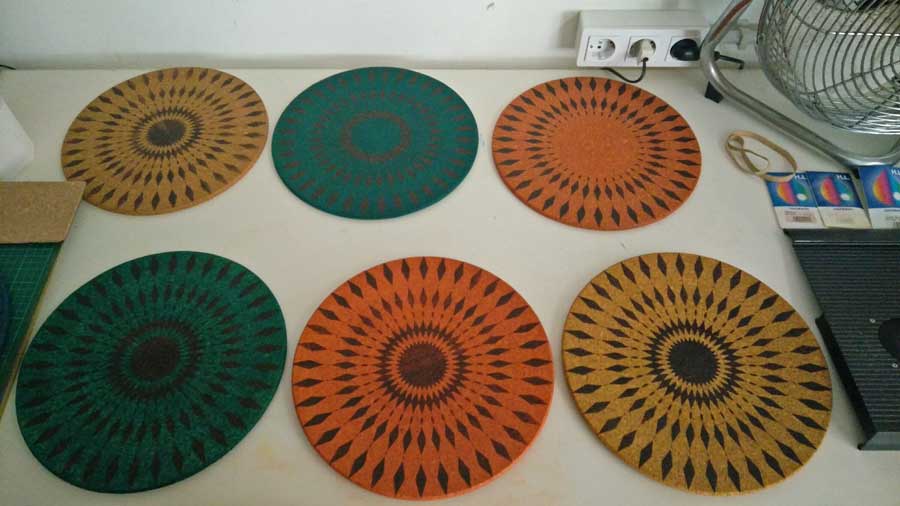
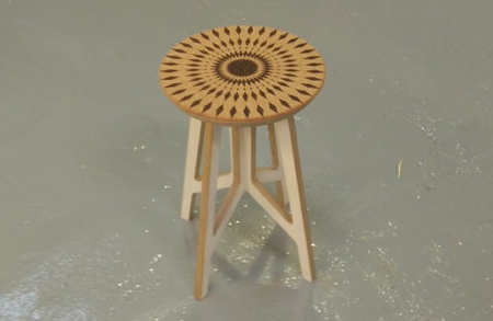
Using these settings I produced a series of cork disks with variations of the pattern and also experimented with colouring the cork with alcohol based anilina dye and finished it with floor waxing. (these last steps of the process are not documented here). These disks are intended as cushion for the Twistab stools to give it a bit more comfort.
NOTE: Ventilation is a crucial issue because when the laser cuts or engrave a material it actually burns some of its particles and that produces hasardous smokes. In our lab even though the Trotec filter turns on automatically when the actual laser is switched on the main ventilation system has to be turned on independently for the exhaust to work effectively.
Further testing
Press-Fit construction Tips tutorial.I downloaded a laser test template file that includes kerf and parameter test and opened it in Rhino in the computer associated with the Trotec 400 we have in the lab.
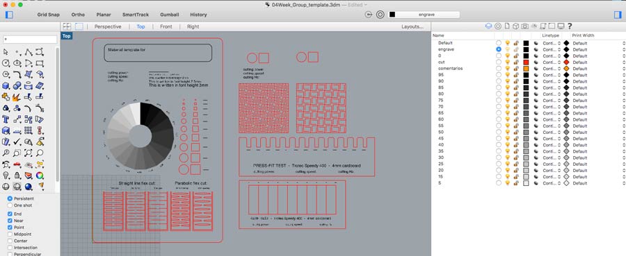
The Trotec400 has a 100 watt laser and the cutting parameter must be set accordingly. I started by running a series of test to define the parameters for cut (vector) engrave and engrave (raster) on 3mm. balsa wood . I created a file composed of a few lines of text (raster) and of repeated objects placed in different colored layers. Each colors is associated with a set of parameters. I ran the test a few times adjusting everytime the parameters.
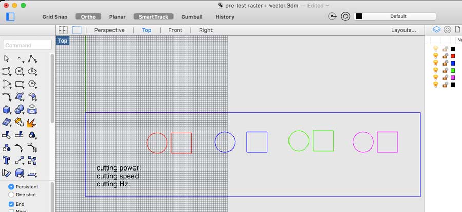
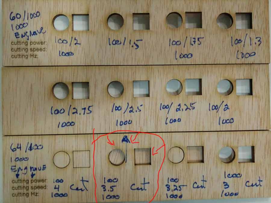
Resulting from these tests I deducted the best parameters for the material and the laser cutter. For cuting I consider the best parameter that one that allows me to cut faster and using th epeast power. It coincide also to be the one who produces less smoke while cutting and makes the thinnest cutting line.
-64 power, 100 speed, 1000 dpi for engraving/raster
-100 power, 3.5 speed, 1000 Hz for cutting/vector
Then I applied these setting to the master test file dividing the job in 2 sessions:
-1º engraving - the grey scale + all written words (in the file it is a raster graphic but we set the job as a vector and by choosing the mode "engrave"it automatically recognize it a raster and process it a s such) .
-2º vector - all the other lines ( red layer)
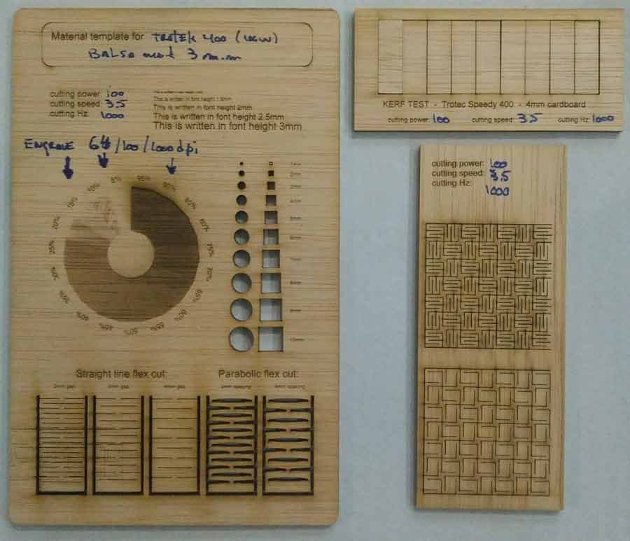
Alltogether the job took about 7 minutes of laser cuting time + 10 minutes of setting up, focussing etc. The result was very precise cut - in the kerf test the gap created is so tiny that it can barely be measured with the instrument precision we dispose of. But the grey scale has very little contrast and high saturation. 5% do not registed and from 80% we cannot notice the difference of tones.
After this I reapeated the test on 4mm. white cardboard. First I ran a test to deduct the parameters.
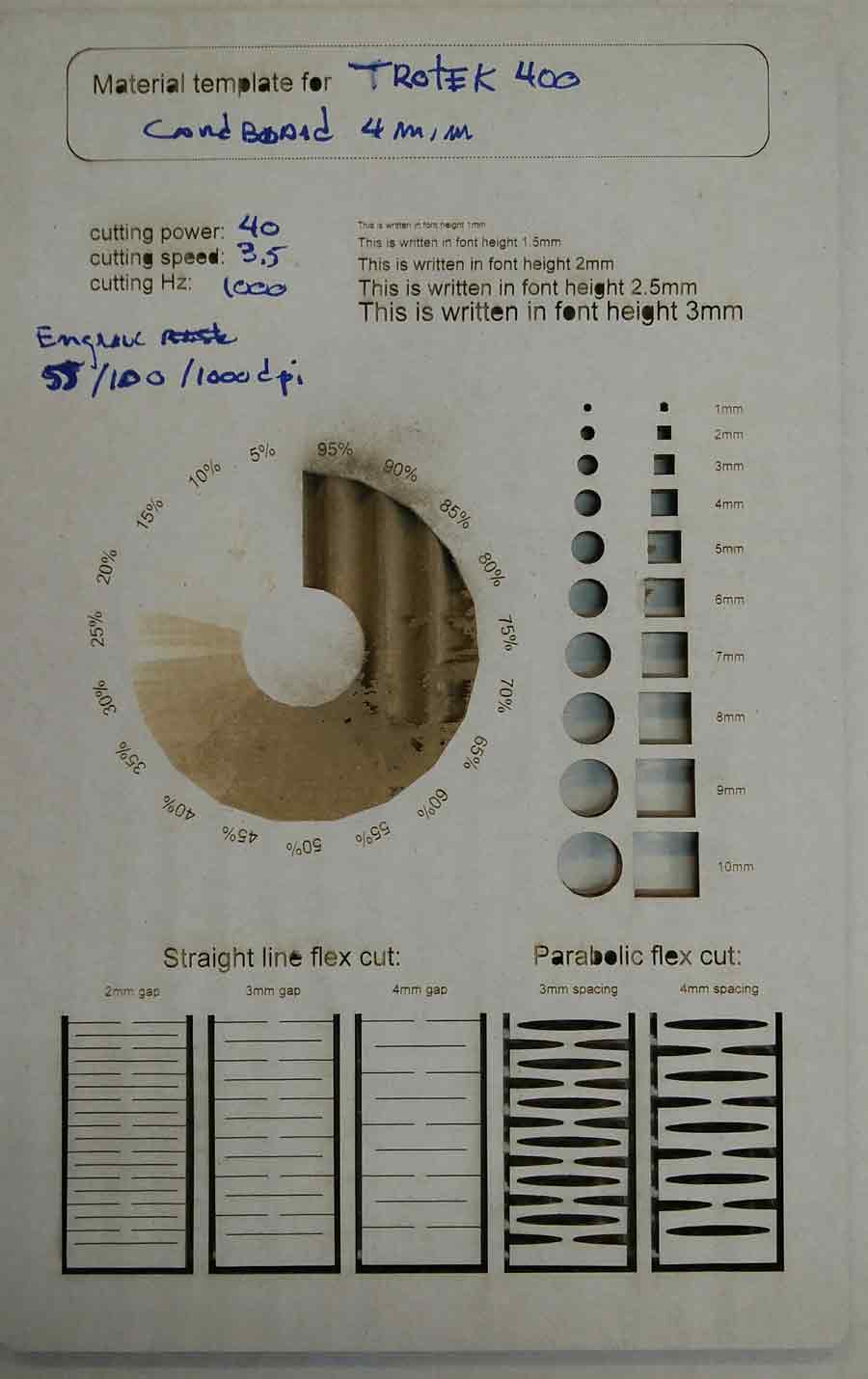
-40(power)/3.5 (speed)/1000 (dpi) for Vector Cut
-55(power)/100/speed)/1000(dpi) for Vector Engrave (equivalent to raster)
The result from the master test file was very different with the cardboard from the Balsa wood. The shades of grey test came out mostly burned out and with even less margin for contrasts and tones of grey. The kerf test resulted in a 1.6mm gap ( divided by 9 pieces)= .17mm kerf which is considerable.
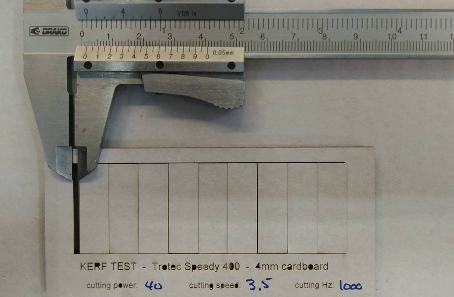
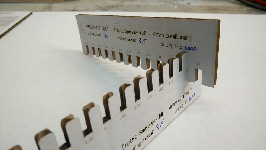
The pressfit test reflected similar results. For a 4mm. material the perfect slot (fit easy with a little bit of pressure so 2 pieces would hold tight when pressfitted) 3.65mm which gives a .35mm tolerance. I'd say half of it comes from the kerf and the other half is to get enough tightness between the parts.
The grey scale raster test shows how the cardboard burned up to the 55% shade of grey part. In that sense it is a non-conclusive test. The paper layer on the surface of the cardboard is too thin to take the strenght of the laser when higher than 55% of the settings (55/11/1000). Also most rasterd words with bigger font size did not come out very well. Where there are lines very close to eachother (like in the p or b) it did not respect the contour of the letter.
C_Design, make and document a parametric press-fit construction kit.
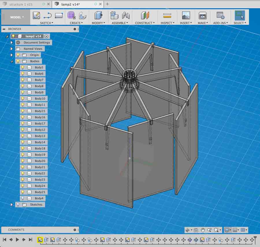
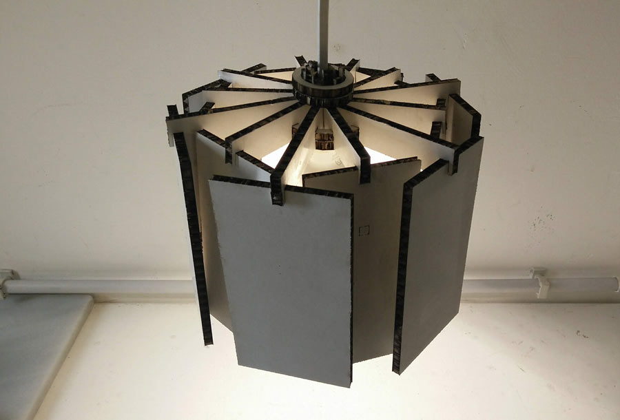
For the pressfit contruction kit i did a simple hanging lamp shade. My objective if to practice parametric design using Fusion 360.
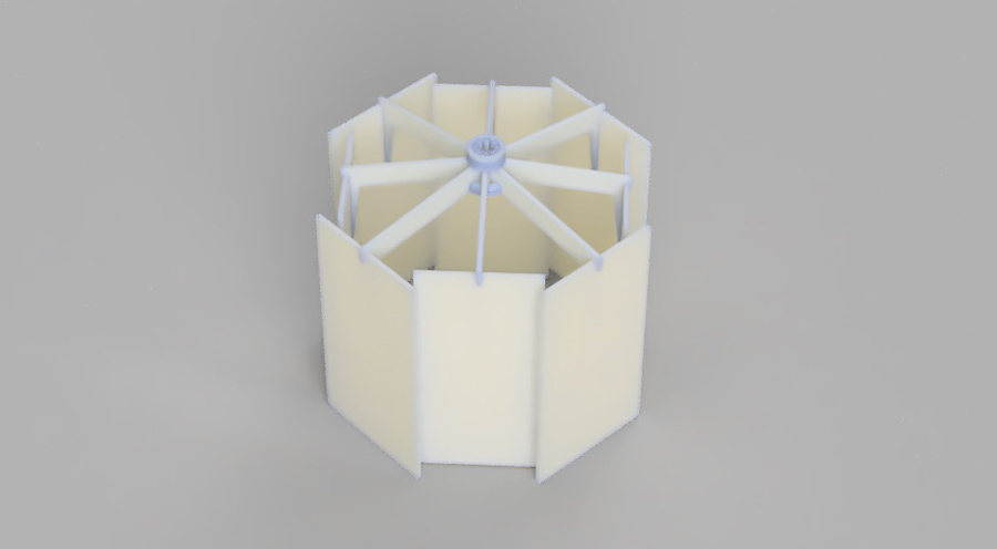
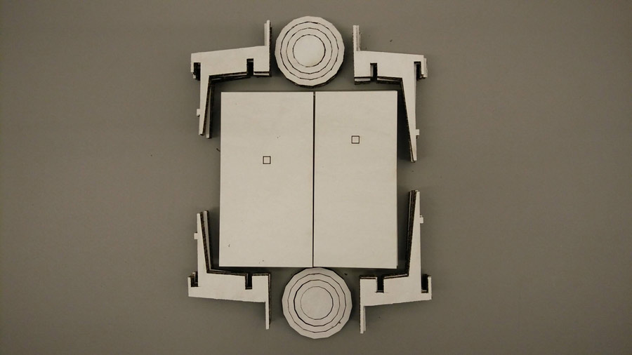
The design is composed of 6 elements.
-structure 1
-structure 2 (a bit shorter than structure 1)
-top ring (hold the structural elements together - resist force towards exterior)
-bottom ring (hold the structural elements together - resist force towards interior)
-panel ext (fit to structure 1)
-panel int (fir to structure 2)
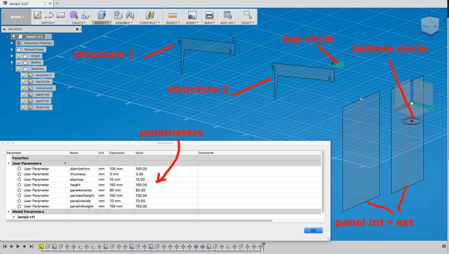
I parametrized the design so it can adapt to the tickness of the material, the diameter of the structure van be adjusted as well as the size (height and width) of both panel int and panel ext can be adjusted. Many curves are set to thickness, thickness/2, thickness*5, and the structure are both refered to the diameter bottom parameter - one is directly bottom diameter and the other is bottom diameter -10mm.
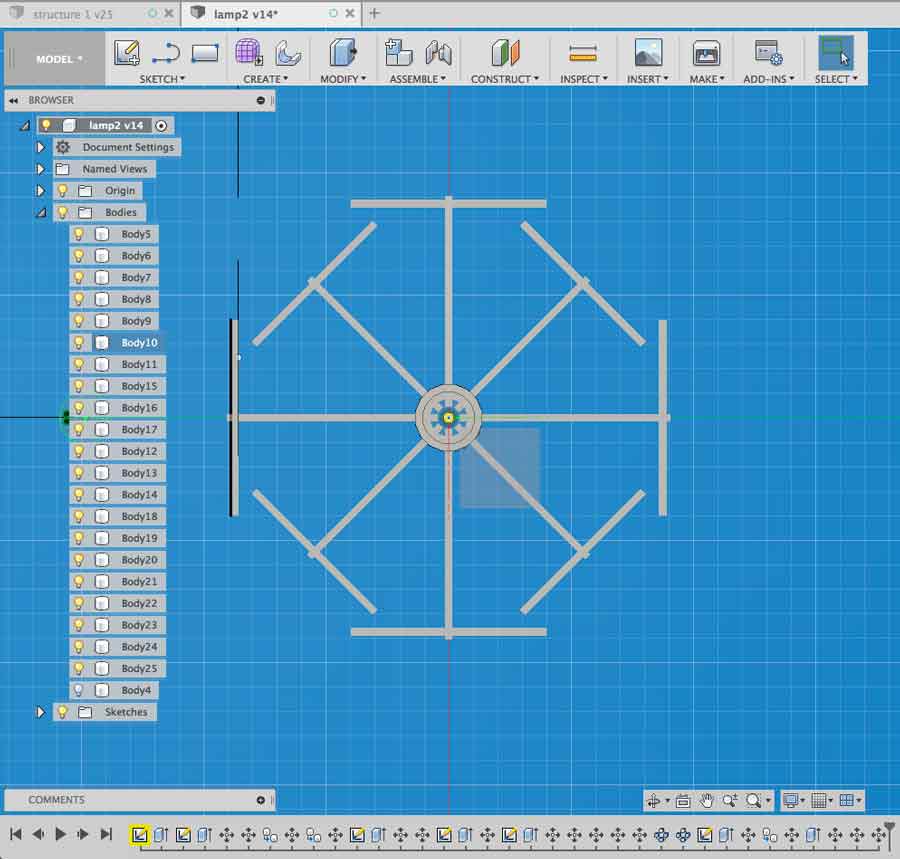
I struggled a lot to find the right constraint that would not create conflict with the parametrization. When changing the diameter of the structure the whole design would go all over the place. I had to start my drawing from scratch 3 times because I got to points where links were missing and so on. This process of troubleshooting the technical aspects of the application made me good through a paralel process of iteration refining the idea and its implementation. The last version I did all the parameters are effective and each aspect of the design react accordingly.
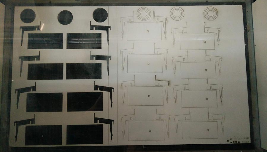
I exported each sketch (elements) to DXF with thickness parameter to 6mm. cardboard and opened it in Rhino to nest the job. I am again using the Trotec 400 again and will cut a test.
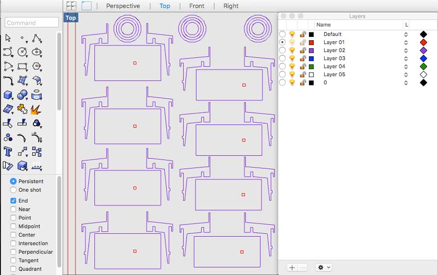
I struggled with the Trotec app and the black layer when testing my settings on a small square. I fix it moving the cut elements to the blue layer in Rhino.
The job has 2 settings:
-One blue for cut through the material.
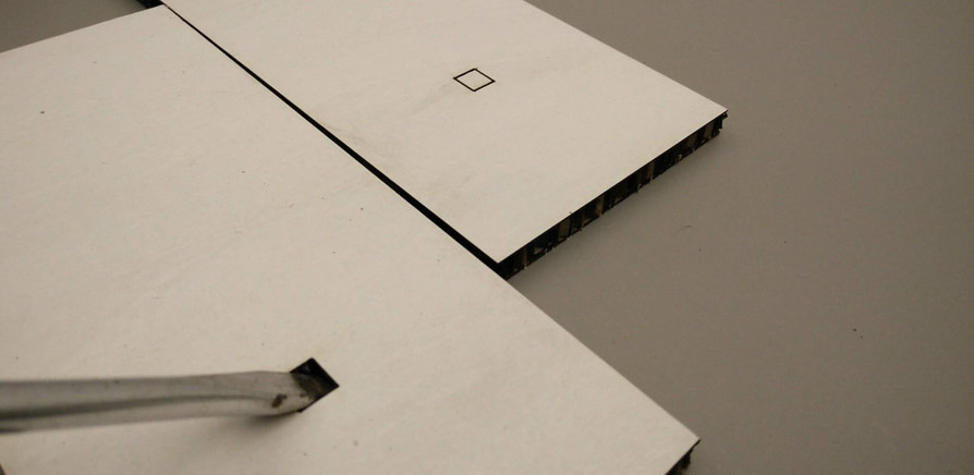
-One red for surface cut (little square on panels to be pocked for a pocketing effect).
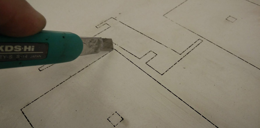
The cardboard was very dense and quite tick when cutting through it produced flames. I paused the job and refocused the lens on each different areas of the Trotec and that eliminated the problem. Nevertheless going safe in the settings there was a little brim left and not to break the fragile parts I went through the lines with a cutter, and I poked the little square with a 6 mm screwdriver.
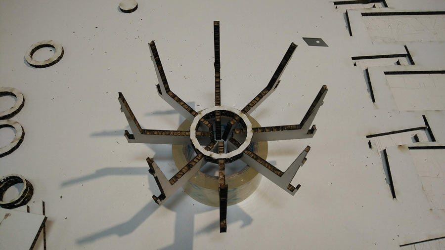
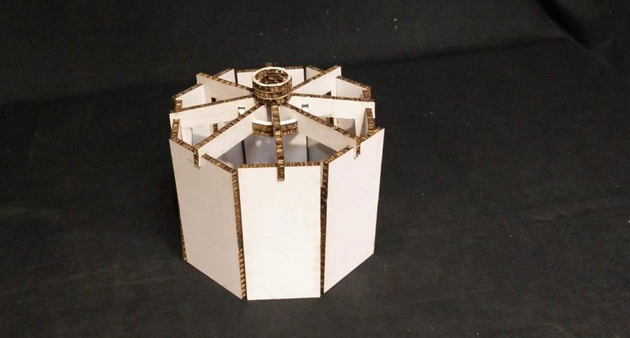
I assembled the first itiration, identified flaws in the parametrization but and taking in consideration the providence of some of th emistake I went back to the file, fixed bugs and printed variations to find composition. I like to imagine this lamp with flexure patterns on the panels.
Conclusion
I learned a lot with this assignment, gained valuable experiences dealing with parametric design, to streamline the workflow and better work with the laser cutter in general and more particularly with vector/raster engraving which I had never really experimented with. I realize how much more I need to learn before I can feel comfortable to fully parametrize a design.